|
|
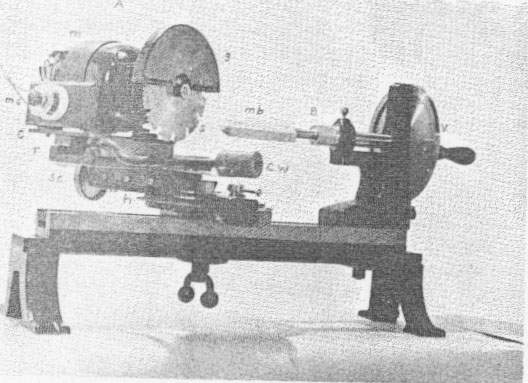
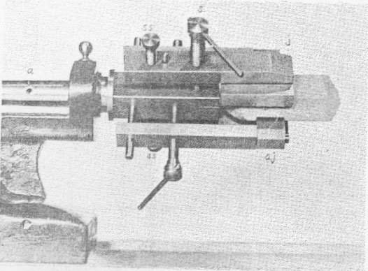
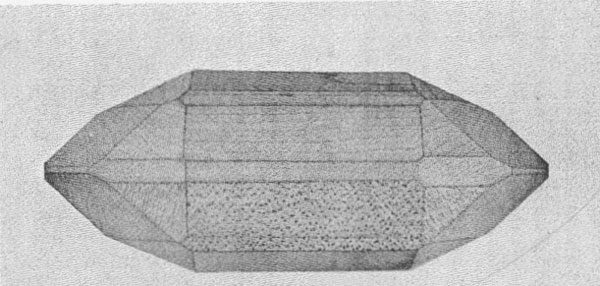
Volume 12, pages 154-167, 1927 A SAW ATTACHMENT ADAPTING GOLDSCHMIDT'S MODEL CUTTING MACHINE TO THE SAWING OF WOODEN MODELS CHARLES PALACHE AND LYMAN W. LEWIS. The instrument1 devised by Professor Goldschmidt for cutting crystal models from plaster has attained wide usefulness in many mineralogical laboratories. The writers' experience with this instrument made it seem desirable so to modify its construction as to permit the cutting of wooden models. This has been accomplished without destroying its usefulness for its original purpose. Three attachments have been devised consisting of a circular saw to replace the plane, a new model holder and a vise to enable the model to be reversed for cutting the second termination. Since the results attained with these attachments are satisfactory and the cutting of wooden models accurately and rapidly is made possible, the present description is offered.2 The instrument with the first two attachments is shown in figure 1. A. CIRCULAR SAW ATTACHMENT. This consists of a small electric motor, m, mounted on a movable carriage, c, adjusted to the runners, r, (carrying the plane of the original machine) and balanced by a counter-weight, cw. A smooth-cutting saw, s, is connected to the motor shaft by means of a steel spindle, and is protected by a light guard, g. The axis of the saw is adjusted to give clearance for a model 2"x2"x6". A motor switch, ins, is conveniently located on the carriage. B. MODEL HOLDER The block is held on a stout screw fixed in a brass holder threaded to the spindle of the vertical circle in the same manner as is the socket for plaster blocks. The diameter of the front of the brass holder is reduced to allow sufficient clearance to complete the prismatic cuts the entire length of the block. The prism zone and truncations of one end of the model are cut on this holder. C. CENTERING VISE If the crystal has a prism zone and it is desired to cut the opposite termination, the crystal is removed from the screw holder and by means of the centering vise is clamped and centered in reverse position. This device is shown in figure 2. A pair of wide jaws j, close or open by means of the screw, s, bearing right and left threads at its opposite ends. These clamp the model by the two most prominently developed prismatic faces and center it in one plane. Perfect centering and rigidity is effected by the two set screws, ss. Auxiliary jaws, aj, at right angles to the first pair, and similarly operated, center the model in the perpendicular plane. This adjustment is effected before the main jaws, j, are clamped tight. The auxiliary jaws, the faces of which rotate on pivots, not only center the model but by clamping another pair of faces, also add rigidity to the grip of the vise. The entire vise, with the centered model, is itself centered with respect to the axis, a, of the vertical circle, a condition necessary in order to cut the second termination symmetrically to the first. The plans were drawn by Mr. D. E. Littlefield, and the attachments were constructed under his direction. The photographs illustrating the machine were made by Mr. E. B. Dane, Jr., who also contributed valuable suggestions on the designs. The saw operates at 1700 revolutions per minute and leaves a surface so smooth that no further finishing is necessary. Any wood that takes a smooth cut without regard to direction of the grain is suitable. Pear wood is probably best but was not available. Maple is easily obtained and gives entirely satisfactory results. A stock of blocks 2"x2"x6" and 2"x1"x6" will serve as blanks for most models. The blanks are squared at one end and bored to fit the model holders. (See Fig. 1, B., plate 9.) The operation of cutting wooden models is essentially the same as the procedure followed in using plaster: the most notable difference being that with the saw a single cut develops the face to any desired depth, while in using plaster, repeated shavings must be removed, which introduces a slight uncertainty in making ideal models. This same difference makes it possible to cut a complete wooden model in the time required to make one in plaster with the single termination. The model illustrated in Fig. 3, plate 10, was made from published data in an hour. Simple forms in all the systems may be cut without removing the block from the screw holder. Doubly terminated models of any crystal can be cut provided there is sufficient prismatic development to provide clearance when gripped in the vise. PLATE IX Figure 1. The Goldschimdt Model-making Machine Showing the Saw Attachments Adapting it to Wooden Model Cutting. PLATE X NOTES 1 Constructed by F. Rheinheimer successor to P. Stoe, Heidelberg. Described by Goldschmidt, Zeits. f. Kryst. 45, p. 573, 1898, and by Tutton, CRYSTALLOGRAPHY AND PRACTICAL CRYSTAL MEASUREMENT, Vol. 1, p. 489. 2 Complete working drawings of saw, screw chuck, and centering vise may be obtained from the Department of Mineralogy, Harvard University for $1.50, the cost of the photostat prints. All the plans have been sent to Rheinheimer who may in the future modify his design to include the saw attachment. Meanwhile, the attachments may be procured from Mr. D. E. Littlefield, Preparator in the Department of Mineralogy, Harvard University, complete for the sum of $100, or the two parts, saw and model holder, necessary for cutting models with a single termination, for $60. [var:'startyear'='1927'] [Include:'footer.htm'] |


